
一、I/O设备模型
RT-Thread中对于I/O设备的抽象是很有特点一个地方,是ucos,freertos都没有的一个地方。RT-Thread提供了一个简单的I/O设备管理框架,希望所有的I/O设备驱动都通过这个框架编写,实现统一的管理。
1.1 I/O设备模型框架
RT-Thread 提供的 I/O 设备模型框架如下图所示,它位于硬件和应用程序之间,共分成三层,从上到下分别是 I/O 设备管理层、设备驱动框架层、设备驱动层:
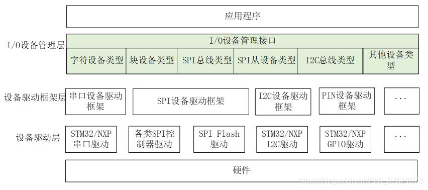
- 应用程序:通过 I/O 设备管理接口获得正确的设备驱动,然后通过这个设备驱动与底层 I/O 硬件设备进行数据(或控制)交互;
- I/O 设备管理层:实现了对设备驱动程序的封装,应用程序通过 I/O设备层提供的标准接口访问底层设备,设备驱动程序的升级、更替不会对上层应用产生影响。这种方式使得设备的硬件操作相关的代码能够独立于应用程序而存在,双方只需关注各自的功能实现,从而降低了代码的耦合性、复杂性,提高了系统的可靠性;
- 设备驱动框架层:是对同类硬件设备驱动的抽象,将不同厂家的同类硬件设备驱动中相同的部分抽取出来,将不同部分留出接口,由驱动程序实现;
- 设备驱动层:是一组驱使硬件设备工作的程序,实现访问硬件设备的功能。它负责创建和注册 I/O 设备,对于操作逻辑简单的设备,可以不经过设备驱动框架层,直接将设备注册到 I/O 设备管理器中;对于另一些设备,如看门狗等,则会将创建的设备实例先注册到对应的设备驱动框架中,再由设备驱动框架向 I/O 设备管理器进行注册。
1.2 I/O设备对象描述
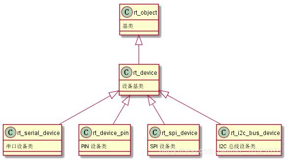
RT-Thread 的设备模型是建立在内核对象模型基础之上的,设备被认为是一类对象,被纳入对象管理器的范畴。每个设备对象都是由基对象派生而来,每个具体设备都可以继承其父类对象的属性,并派生出其私有属性,下图是设备对象的继承和派生关系示意图。
设备对象的描述数据结构如下:
// rt-thread-4.0.1\include\rtdef.h
/**
 * Device structure
 */
struct rt_device
{
    struct rt_object          parent;                   /**< inherit from rt_object */

    enum rt_device_class_type type;                     /**< device type */
    rt_uint16_t               flag;                     /**< device flag */
    rt_uint16_t               open_flag;                /**< device open flag */

    rt_uint8_t                ref_count;                /**< reference count */
    rt_uint8_t                device_id;                /**< 0 - 255 */

    /* device call back */
    rt_err_t (*rx_indicate)(rt_device_t dev, rt_size_t size);
    rt_err_t (*tx_complete)(rt_device_t dev, void *buffer);

#ifdef RT_USING_DEVICE_OPS
    const struct rt_device_ops *ops;
#else
    /* common device interface */
    rt_err_t  (*init)   (rt_device_t dev);
    rt_err_t  (*open)   (rt_device_t dev, rt_uint16_t oflag);
    rt_err_t  (*close)  (rt_device_t dev);
    rt_size_t (*read)   (rt_device_t dev, rt_off_t pos, void *buffer, rt_size_t size);
    rt_size_t (*write)  (rt_device_t dev, rt_off_t pos, const void *buffer, rt_size_t size);
    rt_err_t  (*control)(rt_device_t dev, int cmd, void *args);
#endif

#if defined(RT_USING_POSIX)
    const struct dfs_file_ops *fops;
    struct rt_wqueue wait_queue;
#endif

    void                     *user_data;                /**< device private data */
};

- 1
- 2
- 3
- 4
- 5
- 6
- 7
- 8
- 9
- 10
- 11
- 12
- 13
- 14
- 15
- 16
- 17
- 18
- 19
- 20
- 21
- 22
- 23
- 24
- 25
- 26
- 27
- 28
- 29
- 30
- 31
- 32
- 33
- 34
- 35
- 36
- 37
- 38
设备对象rt_device继承自基对象rt_object,其中rt_device.parent.type值为RT_Object_Class_Device,rt_device.parent.未使用,rt_device.parent.list为设备对象链表节点,所有设备对象被组织成双向链表。
rt_device.type:RT-Thread定义的设备类型如下
// rt-thread-4.0.1\include\rtdef.h
/**
 * device (I/O) class type
 */
enum rt_device_class_type
{
    RT_Device_Class_Char = 0,                           /**< character device */
    RT_Device_Class_Block,                              /**< block device */
    RT_Device_Class_NetIf,                              /**< net interface */
    RT_Device_Class_MTD,                                /**< memory device */
    RT_Device_Class_CAN,                                /**< CAN device */
    RT_Device_Class_RTC,                                /**< RTC device */
    RT_Device_Class_Sound,                              /**< Sound device */
    RT_Device_Class_Graphic,                            /**< Graphic device */
    RT_Device_Class_I2CBUS,                             /**< I2C bus device */
    RT_Device_Class_USBDevice,                          /**< USB slave device */
    RT_Device_Class_USBHost,                            /**< USB host bus */
    RT_Device_Class_SPIBUS,                             /**< SPI bus device */
    RT_Device_Class_SPIDevice,                          /**< SPI device */
    RT_Device_Class_SDIO,                               /**< SDIO bus device */
    RT_Device_Class_PM,                                 /**< PM pseudo device */
    RT_Device_Class_Pipe,                               /**< Pipe device */
    RT_Device_Class_Portal,                             /**< Portal device */
    RT_Device_Class_Timer,                              /**< Timer device */
    RT_Device_Class_Miscellaneous,                      /**< Miscellaneous device */
    RT_Device_Class_Sensor,                             /**< Sensor device */
    RT_Device_Class_Unknown                             /**< unknown device */
};
- 1
- 2
- 3
- 4
- 5
- 6
- 7
- 8
- 9
- 10
- 11
- 12
- 13
- 14
- 15
- 16
- 17
- 18
- 19
- 20
- 21
- 22
- 23
- 24
- 25
- 26
- 27
- 28
其中字符设备、块设备、网络设备是常用的设备类型(也是Linux的三种主要设备类型),它们的分类依据是设备数据与系统之间的传输处理方式。
- 字符设备:提供连续的数据流,应用程序可以顺序读取,通常不支持随机存取。相反,此类设备支持按字节/字符来读写数据。举例来说,键盘、串口、调制解调器都是典型的字符设备;
- 块设备:应用程序可以随机访问设备数据,程序可自行确定读取数据的位置。硬盘、软盘、CD-ROM驱动器和闪存都是典型的块设备,应用程序可以寻址磁盘上的任何位置,并由此读取数据。此外,数据的读写只能以块(通常是512B)的倍数进行。与字符设备不同,块设备并不支持基于字符的寻址;
- 网络设备:特殊设备的驱动,它负责接收和发送帧数据,可能是物理帧,也可能是ip数据包,这些特性都有网络驱动决定。
rt_device.flag:设备标识如下
// rt-thread-4.0.1\include\rtdef.h
/**
 * device flags defitions
 */
#define RT_DEVICE_FLAG_DEACTIVATE       0x000           /**< device is not not initialized */

#define RT_DEVICE_FLAG_RDONLY           0x001           /**< read only */
#define RT_DEVICE_FLAG_WRONLY           0x002           /**< write only */
#define RT_DEVICE_FLAG_RDWR             0x003           /**< read and write */

#define RT_DEVICE_FLAG_REMOVABLE        0x004           /**< removable device */
#define RT_DEVICE_FLAG_STANDALONE       0x008           /**< standalone device */
#define RT_DEVICE_FLAG_ACTIVATED        0x010           /**< device is activated */
#define RT_DEVICE_FLAG_SUSPENDED        0x020           /**< device is suspended */
#define RT_DEVICE_FLAG_STREAM           0x040           /**< stream mode */

#define RT_DEVICE_FLAG_INT_RX           0x100           /**< INT mode on Rx */
#define RT_DEVICE_FLAG_DMA_RX           0x200           /**< DMA mode on Rx */
#define RT_DEVICE_FLAG_INT_TX           0x400           /**< INT mode on Tx */
#define RT_DEVICE_FLAG_DMA_TX           0x800           /**< DMA mode on Tx */
- 1
- 2
- 3
- 4
- 5
- 6
- 7
- 8
- 9
- 10
- 11
- 12
- 13
- 14
- 15
- 16
- 17
- 18
- 19
- 20
rt_device.open_flag:设备打开标识如下
// rt-thread-4.0.1\include\rtdef.h
/**
 * device open flags defitions
 */
#define RT_DEVICE_OFLAG_CLOSE           0x000           /**< device is closed */
#define RT_DEVICE_OFLAG_RDONLY          0x001           /**< read only access */
#define RT_DEVICE_OFLAG_WRONLY          0x002           /**< write only access */
#define RT_DEVICE_OFLAG_RDWR            0x003           /**< read and write */
#define RT_DEVICE_OFLAG_OPEN            0x008           /**< device is opened */
#define RT_DEVICE_OFLAG_MASK            0xf0f           /**< mask of open flag */
- 1
- 2
- 3
- 4
- 5
- 6
- 7
- 8
- 9
- 10
rt_device.ref_count:设备引用计数,每当设备的open方法调用后会使设备引用计数增加1。
rt_device.device_id:设备ID,在部分设备类型(比如IIC)中使用。
rt_device.rx_indicate:设备收到数据后的回调函数指针。
rt_device.tx_complete:设备写入数据完成后的回调函数指针。
rt_device.ops:设备操作函数接口,定义的统一接口如下
// rt-thread-4.0.1\include\rtdef.h
/**
 * operations set for device object
 */
struct rt_device_ops
{
    /* common device interface */
    rt_err_t  (*init)   (rt_device_t dev);
    rt_err_t  (*open)   (rt_device_t dev, rt_uint16_t oflag);
    rt_err_t  (*close)  (rt_device_t dev);
    rt_size_t (*read)   (rt_device_t dev, rt_off_t pos, void *buffer, rt_size_t size);
    rt_size_t (*write)  (rt_device_t dev, rt_off_t pos, const void *buffer, rt_size_t size);
    rt_err_t  (*control)(rt_device_t dev, int cmd, void *args);
};
- 1
- 2
- 3
- 4
- 5
- 6
- 7
- 8
- 9
- 10
- 11
- 12
- 13
- 14
如果想使用Linux的POSIX(Portable Operating System Interface of UNIX)标准接口,可以启用设备文件系统,贯彻Linux一切皆文件的设计思想,把设备抽象为文件,设备句柄也就变成文件描述符了,使用POSIX标准接口还方便将Linux/UNIX系统软件移植到RT-Thread上,POSIX接口fops如下(包括等待队列wait_queue):
// rt-thread-4.0.1\components\dfs\include\dfs_file.h
struct dfs_file_ops
{
    int (*open)     (struct dfs_fd *fd);
    int (*close)    (struct dfs_fd *fd);
    int (*ioctl)    (struct dfs_fd *fd, int cmd, void *args);
    int (*read)     (struct dfs_fd *fd, void *buf, size_t count);
    int (*write)    (struct dfs_fd *fd, const void *buf, size_t count);
    int (*flush)    (struct dfs_fd *fd);
    int (*lseek)    (struct dfs_fd *fd, off_t offset);
    int (*getdents) (struct dfs_fd *fd, struct dirent *dirp, uint32_t count);

    int (*poll)     (struct dfs_fd *fd, struct rt_pollreq *req);
};

/* file descriptor */
#define DFS_FD_MAGIC     0xfdfd
struct dfs_fd
{
    uint16_t magic;              /* file descriptor magic number */
    uint16_t type;               /* Type (regular or socket) */

    char *path;                  /* Name (below mount point) */
    int ref_count;               /* Descriptor reference count */

    struct dfs_filesystem *fs;
    const struct dfs_file_ops *fops;

    uint32_t flags;              /* Descriptor flags */
    size_t   size;               /* Size in bytes */
    off_t    pos;                /* Current file position */

    void *data;                  /* Specific file system data */
};

// rt-thread-4.0.1\include\rtdef.h
/**
 * WaitQueue structure
 */
struct rt_wqueue
{
    rt_uint32_t flag;
    rt_list_t waiting_list;
};
typedef struct rt_wqueue rt_wqueue_t;
- 1
- 2
- 3
- 4
- 5
- 6
- 7
- 8
- 9
- 10
- 11
- 12
- 13
- 14
- 15
- 16
- 17
- 18
- 19
- 20
- 21
- 22
- 23
- 24
- 25
- 26
- 27
- 28
- 29
- 30
- 31
- 32
- 33
- 34
- 35
- 36
- 37
- 38
- 39
- 40
- 41
- 42
- 43
- 44
- 45
- 46
rt_device.user_data是设备的私有数据。
1.3 I/O设备对象接口函数
上层的rt_device设备对象可以看作是一个接口类,下层的设备驱动层中的各种设备都应该继承(包含)rt_device设备对象中的所有接口函数,并在自身的驱动中重新实现这些函数。
下层的设备驱动层实现某具体设备的描述和接口函数的实现后,还需要负责创建设备实例,并注册到I/O设备管理器中,可以通过静态申明的方式创建设备实例,也可以用下面的函数进行动态创建和销毁:
// rt-thread-4.0.1\src\device.c
/**
 * This function creates a device object with user data size.
 *
 * @param type, the kind type of this device object.
 * @param attach_size, the size of user data.
 *
 * @return the allocated device object, or RT_NULL when failed.
 */
rt_device_t rt_device_create(int type, int attach_size)
{
    int size;
    rt_device_t device;

    size = RT_ALIGN(sizeof(struct rt_device), RT_ALIGN_SIZE);
    attach_size = RT_ALIGN(attach_size, RT_ALIGN_SIZE);
    /* use the totoal size */
    size += attach_size;

    device = (rt_device_t)rt_malloc(size);
    if (device)
    {
        rt_memset(device, 0x0, sizeof(struct rt_device));
        device->type = (enum rt_device_class_type)type;
    }

    return device;
}
RTM_EXPORT(rt_device_create);

/**
 * This function destroy the specific device object.
 *
 * @param dev, the specific device object.
 */
void rt_device_destroy(rt_device_t dev)
{
    RT_ASSERT(dev != RT_NULL);
    RT_ASSERT(rt_object_get_type(&dev->parent) == RT_Object_Class_Device);
    RT_ASSERT(rt_object_is_systemobject(&dev->parent) == RT_FALSE);

    rt_object_detach(&(dev->parent));

    /* release this device object */
    rt_free(dev);
}
RTM_EXPORT(rt_device_destroy);
- 1
- 2
- 3
- 4
- 5
- 6
- 7
- 8
- 9
- 10
- 11
- 12
- 13
- 14
- 15
- 16
- 17
- 18
- 19
- 20
- 21
- 22
- 23
- 24
- 25
- 26
- 27
- 28
- 29
- 30
- 31
- 32
- 33
- 34
- 35
- 36
- 37
- 38
- 39
- 40
- 41
- 42
- 43
- 44
- 45
- 46
- 47
设备实例创建后,需要将该设备注册到I/O管理器中,设备注册与注销函数实现如下:
// rt-thread-4.0.1\src\device.c
/**
 * This function registers a device driver with specified name.
 *
 * @param dev the pointer of device driver structure
 * @param name the device driver's name
 * @param flags the capabilities flag of device
 *
 * @return the error code, RT_EOK on initialization successfully.
 */
rt_err_t rt_device_register(rt_device_t dev,
                            const char *name,
                            rt_uint16_t flags)
{
    if (dev == RT_NULL)
        return -RT_ERROR;

    if (rt_device_find(name) != RT_NULL)
        return -RT_ERROR;

    rt_object_init(&(dev->parent), RT_Object_Class_Device, name);
    dev->flag = flags;
    dev->ref_count = 0;
    dev->open_flag = 0;

#if defined(RT_USING_POSIX)
    dev->fops = RT_NULL;
    rt_wqueue_init(&(dev->wait_queue));
#endif

    return RT_EOK;
}
RTM_EXPORT(rt_device_register);

/**
 * This function removes a previously registered device driver
 *
 * @param dev the pointer of device driver structure
 *
 * @return the error code, RT_EOK on successfully.
 */
rt_err_t rt_device_unregister(rt_device_t dev)
{
    RT_ASSERT(dev != RT_NULL);
    RT_ASSERT(rt_object_get_type(&dev->parent) == RT_Object_Class_Device);
    RT_ASSERT(rt_object_is_systemobject(&dev->parent));

    rt_object_detach(&(dev->parent));

    return RT_EOK;
}
RTM_EXPORT(rt_device_unregister);
- 1
- 2
- 3
- 4
- 5
- 6
- 7
- 8
- 9
- 10
- 11
- 12
- 13
- 14
- 15
- 16
- 17
- 18
- 19
- 20
- 21
- 22
- 23
- 24
- 25
- 26
- 27
- 28
- 29
- 30
- 31
- 32
- 33
- 34
- 35
- 36
- 37
- 38
- 39
- 40
- 41
- 42
- 43
- 44
- 45
- 46
- 47
- 48
- 49
- 50
- 51
- 52
在设备驱动层,创建设备实例,并将设备注册到I/O设备管理器后,应用程序就可以通过I/O设备管理器提供的统一接口访问具体设备了。
应用程序要访问某设备,需要先根据期望访问的设备名查找到该设备,查找设备的函数原型如下:
// rt-thread-4.0.1\src\device.c
/**
 * This function finds a device driver by specified name.
 *
 * @param name the device driver's name
 *
 * @return the registered device driver on successful, or RT_NULL on failure.
 */
rt_device_t rt_device_find(const char *name);
- 1
- 2
- 3
- 4
- 5
- 6
- 7
- 8
- 9
查找到期望访问的具体设备,并获得该设备句柄后就可以通过下面的接口访问该设备了:
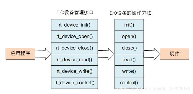
上图中的I/O设备管理接口函数原型如下:
// rt-thread-4.0.1\src\device.c
/**
 * This function will initialize the specified device
 *
 * @param dev the pointer of device driver structure
 *
 * @return the result
 */
rt_err_t rt_device_init(rt_device_t dev);

/**
 * This function will open a device
 *
 * @param dev the pointer of device driver structure
 * @param oflag the flags for device open
 *
 * @return the result
 */
rt_err_t rt_device_open(rt_device_t dev, rt_uint16_t oflag);

/**
 * This function will close a device
 *
 * @param dev the pointer of device driver structure
 *
 * @return the result
 */
rt_err_t rt_device_close(rt_device_t dev);

/**
 * This function will read some data from a device.
 *
 * @param dev the pointer of device driver structure
 * @param pos the position of reading
 * @param buffer the data buffer to save read data
 * @param size the size of buffer
 *
 * @return the actually read size on successful, otherwise negative returned.
 *
 * @note since 0.4.0, the unit of size/pos is a block for block device.
 */
rt_size_t rt_device_read(rt_device_t dev,
                         rt_off_t    pos,
                         void       *buffer,
                         rt_size_t   size);

/**
 * This function will write some data to a device.
 *
 * @param dev the pointer of device driver structure
 * @param pos the position of written
 * @param buffer the data buffer to be written to device
 * @param size the size of buffer
 *
 * @return the actually written size on successful, otherwise negative returned.
 *
 * @note since 0.4.0, the unit of size/pos is a block for block device.
 */
rt_size_t rt_device_write(rt_device_t dev,
                          rt_off_t    pos,
                          const void *buffer,
                          rt_size_t   size);

/**
 * This function will perform a variety of control functions on devices.
 *
 * @param dev the pointer of device driver structure
 * @param cmd the command sent to device
 * @param arg the argument of command
 *
 * @return the result
 */
rt_err_t rt_device_control(rt_device_t dev, int cmd, void *arg);
- 1
- 2
- 3
- 4
- 5
- 6
- 7
- 8
- 9
- 10
- 11
- 12
- 13
- 14
- 15
- 16
- 17
- 18
- 19
- 20
- 21
- 22
- 23
- 24
- 25
- 26
- 27
- 28
- 29
- 30
- 31
- 32
- 33
- 34
- 35
- 36
- 37
- 38
- 39
- 40
- 41
- 42
- 43
- 44
- 45
- 46
- 47
- 48
- 49
- 50
- 51
- 52
- 53
- 54
- 55
- 56
- 57
- 58
- 59
- 60
- 61
- 62
- 63
- 64
- 65
- 66
- 67
- 68
- 69
- 70
- 71
- 72
- 73
上面这些I/O设备管理接口实际调用的是设备操作虚函数表rt_device.rt_device_ops中相应函数指针指向的函数,具体的函数实现由设备驱动层完成,并将设备驱动层实现的函数表注册到I/O设备管理器,也即将设备操作虚函数表rt_device.rt_device_ops指向设备驱动层实现的具体设备操作函数表。
对rt_device设备的操作,除了上面的统一访问接口外,还支持发送、接收回调函数的设置,具体的回调函数实现由用户在应用程序中完成,当设备接收到数据或数据发送完成后自动调用用户设置的回调函数,设置发送、接收回调函数的函数实现如下:
// rt-thread-4.0.1\src\device.c
/**
 * This function will set the reception indication callback function. This callback function
 * is invoked when this device receives data.
 *
 * @param dev the pointer of device driver structure
 * @param rx_ind the indication callback function
 *
 * @return RT_EOK
 */
rt_err_t
rt_device_set_rx_indicate(rt_device_t dev,
                          rt_err_t (*rx_ind)(rt_device_t dev, rt_size_t size))
{
    RT_ASSERT(dev != RT_NULL);
    RT_ASSERT(rt_object_get_type(&dev->parent) == RT_Object_Class_Device);

    dev->rx_indicate = rx_ind;

    return RT_EOK;
}
RTM_EXPORT(rt_device_set_rx_indicate);

/**
 * This function will set the indication callback function when device has
 * written data to physical hardware.
 *
 * @param dev the pointer of device driver structure
 * @param tx_done the indication callback function
 *
 * @return RT_EOK
 */
rt_err_t
rt_device_set_tx_complete(rt_device_t dev,
                          rt_err_t (*tx_done)(rt_device_t dev, void *buffer))
{
    RT_ASSERT(dev != RT_NULL);
    RT_ASSERT(rt_object_get_type(&dev->parent) == RT_Object_Class_Device);

    dev->tx_complete = tx_done;

    return RT_EOK;
}
RTM_EXPORT(rt_device_set_tx_complete);
- 1
- 2
- 3
- 4
- 5
- 6
- 7
- 8
- 9
- 10
- 11
- 12
- 13
- 14
- 15
- 16
- 17
- 18
- 19
- 20
- 21
- 22
- 23
- 24
- 25
- 26
- 27
- 28
- 29
- 30
- 31
- 32
- 33
- 34
- 35
- 36
- 37
- 38
- 39
- 40
- 41
- 42
- 43
- 44
二、PIN设备管理示例
RT-Thread中的PIN设备也即STM32中的GPIO,在博客HAL详解与CubeMX使用中介绍了GPIO的原理、HAL库中GPIO的配置、GPIO中断/事件触发等,对于GPIO的输入输出模式、中断事件触发模式有详细的介绍,这里就不赘述了,下面重点看RT-Thread中对PIN设备的管理是如何实现的。
2.1 PIN设备驱动框架层
前面介绍了最上层的I/O设备管理层是如何实现的,下面先介绍PIN设备驱动框架层。
- PIN设备控制块
首先看在设备驱动框架层,PIN设备是如何描述的:
// rt-thread-4.0.1\components\drivers\include\drivers\pin.h

/* pin device and operations for RT-Thread */
struct rt_device_pin
{
    struct rt_device parent;
    const struct rt_pin_ops *ops;
};
- 1
- 2
- 3
- 4
- 5
- 6
- 7
- 8
PIN设备数据描述挺简单,除了继承自rt_device外,只有一个私有成员rt_device_pin.ops。
在rt_device.type中并没有看到PIN设备,在rt-thread-4.0.1\components\drivers\misc目录下找到pin.c文件,所以PIN设备类型rt_device_pin.parent.type值为RT_Device_Class_Miscellaneous。
PIN设备的访问接口虚函数表rt_device_pin.ops如下:
// rt-thread-4.0.1\components\drivers\include\drivers\pin.h

struct rt_pin_ops
{
    void (*pin_mode)(struct rt_device *device, rt_base_t pin, rt_base_t mode);
    void (*pin_write)(struct rt_device *device, rt_base_t pin, rt_base_t value);
    int (*pin_read)(struct rt_device *device, rt_base_t pin);

    /* TODO: add GPIO interrupt */
    rt_err_t (*pin_attach_irq)(struct rt_device *device, rt_int32_t pin,
                      rt_uint32_t mode, void (*hdr)(void *args), void *args);
    rt_err_t (*pin_detach_irq)(struct rt_device *device, rt_int32_t pin);
    rt_err_t (*pin_irq_enable)(struct rt_device *device, rt_base_t pin, rt_uint32_t enabled);
};
- 1
- 2
- 3
- 4
- 5
- 6
- 7
- 8
- 9
- 10
- 11
- 12
- 13
- 14
从rt_pin_ops中函数指针的参数看,结合GPIO的基本知识,PIN设备有模式定义(输入模式、输出模式)和状态定义(高电平、低电平),二者的相关描述代码如下:
// rt-thread-4.0.1\components\drivers\include\drivers\pin.h

struct rt_device_pin_mode
{
    rt_uint16_t pin;
    rt_uint16_t mode;
};

#define PIN_MODE_OUTPUT         0x00
#define PIN_MODE_INPUT          0x01
#define PIN_MODE_INPUT_PULLUP   0x02
#define PIN_MODE_INPUT_PULLDOWN 0x03
#define PIN_MODE_OUTPUT_OD      0x04

struct rt_device_pin_status
{
    rt_uint16_t pin;
    rt_uint16_t status;
};

#define PIN_LOW                 0x00
#define PIN_HIGH                0x01
- 1
- 2
- 3
- 4
- 5
- 6
- 7
- 8
- 9
- 10
- 11
- 12
- 13
- 14
- 15
- 16
- 17
- 18
- 19
- 20
- 21
- 22
PIN设备是支持中断、事件触发的,rt_pin_ops中有中断回调函数的绑定、脱离接口,中断回调函数由用户在应用程序中实现,实现后的中断回调函数需要绑定到相应的PIN设备引脚上才能在中断触发时被调用,回调函数的指针、参数、中断触发模式、引脚号最好封装为一个整体便于传参,回调函数指针的描述代码如下:
// rt-thread-4.0.1\components\drivers\include\drivers\pin.h

struct rt_pin_irq_hdr
{
    rt_int16_t        pin;
    rt_uint16_t       mode;
    void (*hdr)(void *args);
    void             *args;
};

#define PIN_IRQ_MODE_RISING             0x00
#define PIN_IRQ_MODE_FALLING            0x01
#define PIN_IRQ_MODE_RISING_FALLING     0x02
#define PIN_IRQ_MODE_HIGH_LEVEL         0x03
#define PIN_IRQ_MODE_LOW_LEVEL          0x04

#define PIN_IRQ_DISABLE                 0x00
#define PIN_IRQ_ENABLE                  0x01

#define PIN_IRQ_PIN_NONE                -1
- 1
- 2
- 3
- 4
- 5
- 6
- 7
- 8
- 9
- 10
- 11
- 12
- 13
- 14
- 15
- 16
- 17
- 18
- 19
- 20
- PIN设备接口函数
前面介绍I/O设备管理层时也提到,上层要想访问某设备,需要在下面的设备驱动层创建设备实例,并将该设备注册到I/O设备管理层,下面先看看PIN设备的创建与注册过程:
// rt-thread-4.0.1\components\drivers\misc\pin.c

static struct rt_device_pin _hw_pin;

/**
 * This function registers the device to the device manager.
 *
 * @param name: device name string;
 * @param ops: device operation virtual function table.
 *
 * @return RT_EOK or -RT_ERROR
 */
int rt_device_pin_register(const char *name, const struct rt_pin_ops *ops, void *user_data)
{
    _hw_pin.parent.type         = RT_Device_Class_Miscellaneous;
    _hw_pin.parent.rx_indicate  = RT_NULL;
    _hw_pin.parent.tx_complete  = RT_NULL;

#ifdef RT_USING_DEVICE_OPS
    _hw_pin.parent.ops          = &pin_ops;
#else
    _hw_pin.parent.init         = RT_NULL;
    _hw_pin.parent.open         = RT_NULL;
    _hw_pin.parent.close        = RT_NULL;
    _hw_pin.parent.read         = _pin_read;
    _hw_pin.parent.write        = _pin_write;
    _hw_pin.parent.control      = _pin_control;
#endif

    _hw_pin.ops                 = ops;
    _hw_pin.parent.user_data    = user_data;

    /* register a character device */
    rt_device_register(&_hw_pin.parent, name, RT_DEVICE_FLAG_RDWR);

    return 0;
}

#ifdef RT_USING_DEVICE_OPS
const static struct rt_device_ops pin_ops =
{
    RT_NULL,
    RT_NULL,
    RT_NULL,
    _pin_read,
    _pin_write,
    _pin_control
};
#endif
- 1
- 2
- 3
- 4
- 5
- 6
- 7
- 8
- 9
- 10
- 11
- 12
- 13
- 14
- 15
- 16
- 17
- 18
- 19
- 20
- 21
- 22
- 23
- 24
- 25
- 26
- 27
- 28
- 29
- 30
- 31
- 32
- 33
- 34
- 35
- 36
- 37
- 38
- 39
- 40
- 41
- 42
- 43
- 44
- 45
- 46
- 47
- 48
- 49
PIN设备以静态申明的方式创建了设备实例_hw_pin;PIN设备注册函数在完成_hw_pin.parent及_hw_pin.ops的初始化后调用设备注册函数rt_device_register将PIN设备注册到设备管理器,应用层便可以通过rt_device设备管理层接口访问PIN设备了。
PIN设备注册过程同样包含了PIN设备操作函数表的赋值,向上层I/O设备管理层注册的操作函数表pin_ops只实现了read / write / control三个函数(这三个函数实际调用的是rt_device_pin.ops函数表内的函数),另外三个函数则没有实现。
PIN设备中断回调函数的绑定、脱离、使能等操作,在上层设备访问虚函数表rt_device_ops中并没有对应的接口,所以PIN设备驱动框架层的操作函数表rt_pin_ops便单独向上层开放了,上层的I/O设备管理层可以直接调用PIN设备的操作函数表,当然跟rt_device_pin.ops不完全一样,而是对其进行了一层封装,封装后开放给上层的PIN设备管理接口函数如下:
// rt-thread-4.0.1\components\drivers\misc\pin.c

/* RT-Thread Hardware PIN APIs */
void rt_pin_mode(rt_base_t pin, rt_base_t mode)
{
    RT_ASSERT(_hw_pin.ops != RT_NULL);
    _hw_pin.ops->pin_mode(&_hw_pin.parent, pin, mode);
}
FINSH_FUNCTION_EXPORT_ALIAS(rt_pin_mode, pinMode, set hardware pin mode);

void rt_pin_write(rt_base_t pin, rt_base_t value)
{
    RT_ASSERT(_hw_pin.ops != RT_NULL);
    _hw_pin.ops->pin_write(&_hw_pin.parent, pin, value);
}
FINSH_FUNCTION_EXPORT_ALIAS(rt_pin_write, pinWrite, write value to hardware pin);

int  rt_pin_read(rt_base_t pin)
{
    RT_ASSERT(_hw_pin.ops != RT_NULL);
    return _hw_pin.ops->pin_read(&_hw_pin.parent, pin);
}
FINSH_FUNCTION_EXPORT_ALIAS(rt_pin_read, pinRead, read status from hardware pin);

rt_err_t rt_pin_attach_irq(rt_int32_t pin, rt_uint32_t mode,
                             void (*hdr)(void *args), void  *args)
{
    RT_ASSERT(_hw_pin.ops != RT_NULL);
    if(_hw_pin.ops->pin_attach_irq)
    {
        return _hw_pin.ops->pin_attach_irq(&_hw_pin.parent, pin, mode, hdr, args);
    }
    return RT_ENOSYS;
}
rt_err_t rt_pin_detach_irq(rt_int32_t pin)
{
    RT_ASSERT(_hw_pin.ops != RT_NULL);
    if(_hw_pin.ops->pin_detach_irq)
    {
        return _hw_pin.ops->pin_detach_irq(&_hw_pin.parent, pin);
    }
    return RT_ENOSYS;
}

rt_err_t rt_pin_irq_enable(rt_base_t pin, rt_uint32_t enabled)
{
    RT_ASSERT(_hw_pin.ops != RT_NULL);
    if(_hw_pin.ops->pin_irq_enable)
    {
        return _hw_pin.ops->pin_irq_enable(&_hw_pin.parent, pin, enabled);
    }
    return RT_ENOSYS;
}
- 1
- 2
- 3
- 4
- 5
- 6
- 7
- 8
- 9
- 10
- 11
- 12
- 13
- 14
- 15
- 16
- 17
- 18
- 19
- 20
- 21
- 22
- 23
- 24
- 25
- 26
- 27
- 28
- 29
- 30
- 31
- 32
- 33
- 34
- 35
- 36
- 37
- 38
- 39
- 40
- 41
- 42
- 43
- 44
- 45
- 46
- 47
- 48
- 49
- 50
- 51
- 52
- 53
从上面的PIN设备接口函数代码也可以看出,这些接口函数就是对rt_device_pin.ops函数表的调用,那么rt_device_pin.ops虚函数表的实现代码在哪呢?这就要继续往下看设备驱动层了。
2.2 PIN设备驱动层
设备驱动层就要实现设备的访问操作函数了,函数实现最终是靠调用芯片厂商提供的固件库,对于STM32L475来说就是调用CubeL4 HAL库函数实现设备驱动功能。
- STM32 GPIO数据结构
STM32 GPIO比较靠近底层,所以HAL库并没有为GPIO提高句柄结构体描述,RT-Thread提供的PIN设备驱动也没有类似GPIO控制块之类的数据结构。
在STM32 HAL库中描述某个GPIO通常需要两个参数,分别是GPIO_TypeDef* GPIOx和GPIO_Pin,比如下面的函数声明:
// libraries\STM32L4xx_HAL\STM32L4xx_HAL_Driver\Inc\stm32l4xx_hal_gpio.h
/* IO operation functions *****************************************************/
GPIO_PinState     HAL_GPIO_ReadPin(GPIO_TypeDef* GPIOx, uint16_t GPIO_Pin);
void              HAL_GPIO_WritePin(GPIO_TypeDef* GPIOx, uint16_t GPIO_Pin, GPIO_PinState PinState);
void              HAL_GPIO_TogglePin(GPIO_TypeDef* GPIOx, uint16_t GPIO_Pin);
HAL_StatusTypeDef HAL_GPIO_LockPin(GPIO_TypeDef* GPIOx, uint16_t GPIO_Pin);
void              HAL_GPIO_EXTI_IRQHandler(uint16_t GPIO_Pin);
void              HAL_GPIO_EXTI_Callback(uint16_t GPIO_Pin);
- 1
- 2
- 3
- 4
- 5
- 6
- 7
- 8
RT-Thread觉得用两个变量共同描述一个GPIO不够方便,所以定义了一个结构体pin_index,通过一个变量即可描述一个GPIO,该结构体代码如下:
// libraries\HAL_Drivers\drv_gpio.h
/* STM32 GPIO driver */
struct pin_index
{
    int index;
    GPIO_TypeDef *gpio;
    uint32_t pin;
};

#define __STM32_PIN(index, gpio, gpio_index)                                \
    {                                                                       \
        index, GPIO##gpio, GPIO_PIN_##gpio_index                            \
    }

#define __STM32_PIN_RESERVE                                                 \
    {                                                                       \
        -1, 0, 0                                                            \
    }

#define __STM32_PORT(port)  GPIO##port

#define GET_PIN(PORTx,PIN) (rt_base_t)((16 * ( ((rt_base_t)__STM32_PORT(PORTx) - (rt_base_t)GPIOA)/(0x0400UL) )) + PIN)
- 1
- 2
- 3
- 4
- 5
- 6
- 7
- 8
- 9
- 10
- 11
- 12
- 13
- 14
- 15
- 16
- 17
- 18
- 19
- 20
- 21
- 22
结构体pin_index以宏定义__STM32_PIN(index, gpio, gpio_index)的形式被初始化,其中##为C语言连接符,其功能是在带参数的宏定义中将两个子串(token)联接起来,从而形成一个新的子串,比如宏__STM32_PIN(0, A, 0)展开后为{0, GPIOA, GPIO_PIN_0},同时定义了保留未使用的宏定义__STM32_PIN_RESERVE。
为了方便我们将HAL库描述GPIO的形式转换为RT-Thread GPIO设备驱动描述GPIO的形式,还定义了一个宏GET_PIN(PORTx,PIN),可以将(GPIOx, GPIO_Pin)转换为pin_index.index。
RT-Thread对GPIO引脚有了新的描述和初始化宏定义,自然要有一个设备容器来定义STM32L4支持的所有GPIO引脚,GPIO设备容器以数组形式定义(类似前面介绍过的内核对象与对象容器),代码如下:
// libraries\HAL_Drivers\drv_gpio.c

static const struct pin_index pins[] =
{
#ifdef GPIOA
    __STM32_PIN(0 ,  A, 0 ),
	......
    __STM32_PIN(15,  A, 15),
#endif
	......
#ifdef GPIOK
    __STM32_PIN(160, K, 0),
	......
    __STM32_PIN(175, K, 15),
#endif
};

#define ITEM_NUM(items) sizeof(items) / sizeof(items[0])
/**
 * This function can get pin information based on the pin index.
 *
 * @param pin: pin index (struct pin_index.index)
 *
 * @return pin_index pointer or RT_NULL
 */
static const struct pin_index *get_pin(uint8_t pin)
{
    const struct pin_index *index;

    if (pin < ITEM_NUM(pins))
    {
        index = &pins[pin];
        if (index->index == -1)
            index = RT_NULL;
    }
    else
    {
        index = RT_NULL;
    }

    return index;
};
- 1
- 2
- 3
- 4
- 5
- 6
- 7
- 8
- 9
- 10
- 11
- 12
- 13
- 14
- 15
- 16
- 17
- 18
- 19
- 20
- 21
- 22
- 23
- 24
- 25
- 26
- 27
- 28
- 29
- 30
- 31
- 32
- 33
- 34
- 35
- 36
- 37
- 38
- 39
- 40
- 41
- 42
RT-Thread GPIO驱动定义了存放GPIO引脚信息的数组容器,而且也提供了通过引脚编号获得该引脚基本信息结构体指针(数组元素)的接口函数get_pin,这样就可以只通过一个引脚索引号index锁定某一特定的GPIO引脚。
我们使用HAL库编写GPIO程序时需要使能相应的外部中断线并编写对应外部中断线的中断处理函数,也即需要查找某个GPIO对应哪个外部中断线EXITx,RT-Thread想进一步简化传参过程,在上层PIN设备管理接口中不需要我们关心某个PIN对应的是哪个外部中断线,这就需要在GPIO驱动层建立GPIO引脚号与外部中断线EXITx之间的映射关系,该过程的相关代码如下(依然是数组形式定义GPIO中断映射表):
// libraries\HAL_Drivers\drv_gpio.h
struct pin_irq_map
{
    rt_uint16_t pinbit;
    IRQn_Type irqno;
};

// libraries\HAL_Drivers\drv_gpio.c
static const struct pin_irq_map pin_irq_map[] =
{
    {GPIO_PIN_0, EXTI0_IRQn},
    {GPIO_PIN_1, EXTI1_IRQn},
    {GPIO_PIN_2, EXTI2_IRQn},
    {GPIO_PIN_3, EXTI3_IRQn},
    {GPIO_PIN_4, EXTI4_IRQn},
    {GPIO_PIN_5, EXTI9_5_IRQn},
    {GPIO_PIN_6, EXTI9_5_IRQn},
    {GPIO_PIN_7, EXTI9_5_IRQn},
    {GPIO_PIN_8, EXTI9_5_IRQn},
    {GPIO_PIN_9, EXTI9_5_IRQn},
    {GPIO_PIN_10, EXTI15_10_IRQn},
    {GPIO_PIN_11, EXTI15_10_IRQn},
    {GPIO_PIN_12, EXTI15_10_IRQn},
    {GPIO_PIN_13, EXTI15_10_IRQn},
    {GPIO_PIN_14, EXTI15_10_IRQn},
    {GPIO_PIN_15, EXTI15_10_IRQn},
};

#define ITEM_NUM(items) sizeof(items) / sizeof(items[0])
/**
 * This function can convert GPIO_PIN_X to the index of pin_irq_map.
 *
 * @param bit: GPIO_PIN_X, (stm32l4xx_hal_gpio.h: #define GPIO_PIN_1      ((uint16_t)0x0002))
 *
 * @return index of pin_irq_map or -1.
 */
rt_inline rt_int32_t bit2bitno(rt_uint32_t bit)
{
    int i;
    for (i = 0; i < 32; i++)
    {
        if ((0x01 << i) == bit)
        {
            return i;
        }
    }
    return -1;
}

/**
 * This function can get irqno information according to GPIO_PIN_X.
 *
 * @param pinbit: GPIO_PIN_X (struct pin_irq_map.pinbit)
 *
 * @return pin_irq_map pointer or RT_NULL
 */
rt_inline const struct pin_irq_map *get_pin_irq_map(uint32_t pinbit)
{
    rt_int32_t mapindex = bit2bitno(pinbit);
    if (mapindex < 0 || mapindex >= ITEM_NUM(pin_irq_map))
    {
        return RT_NULL;
    }
    return &pin_irq_map[mapindex];
};
- 1
- 2
- 3
- 4
- 5
- 6
- 7
- 8
- 9
- 10
- 11
- 12
- 13
- 14
- 15
- 16
- 17
- 18
- 19
- 20
- 21
- 22
- 23
- 24
- 25
- 26
- 27
- 28
- 29
- 30
- 31
- 32
- 33
- 34
- 35
- 36
- 37
- 38
- 39
- 40
- 41
- 42
- 43
- 44
- 45
- 46
- 47
- 48
- 49
- 50
- 51
- 52
- 53
- 54
- 55
- 56
- 57
- 58
- 59
- 60
- 61
- 62
- 63
- 64
- 65
上面定义了GPIO引脚号与外部中断线的映射关系数组,同时提供了根据GPIO引脚号GPIO_PIN_X获得该引脚对应结构体pin_irq_map指针的接口函数get_pin_irq_map,这样就可以通过引脚号GPIO_PIN_X获得该引脚对应的外部中断线。
PIN设备驱动框架层定义了某个PIN的中断回调函数结构体rt_pin_irq_hdr,为了方便PIN设备管理,GPIO驱动层还初始化了rt_pin_irq_hdr,定义了中断回调函数列表,代码如下:
// rt-thread-4.0.1\components\drivers\include\drivers\pin.h
struct rt_pin_irq_hdr
{
    rt_int16_t        pin;
    rt_uint16_t       mode;
    void (*hdr)(void *args);
    void             *args;
};

// libraries\HAL_Drivers\drv_gpio.c
static struct rt_pin_irq_hdr pin_irq_hdr_tab[] =
{
    {-1, 0, RT_NULL, RT_NULL},
    {-1, 0, RT_NULL, RT_NULL},
    {-1, 0, RT_NULL, RT_NULL},
    {-1, 0, RT_NULL, RT_NULL},
    {-1, 0, RT_NULL, RT_NULL},
    {-1, 0, RT_NULL, RT_NULL},
    {-1, 0, RT_NULL, RT_NULL},
    {-1, 0, RT_NULL, RT_NULL},
    {-1, 0, RT_NULL, RT_NULL},
    {-1, 0, RT_NULL, RT_NULL},
    {-1, 0, RT_NULL, RT_NULL},
    {-1, 0, RT_NULL, RT_NULL},
    {-1, 0, RT_NULL, RT_NULL},
    {-1, 0, RT_NULL, RT_NULL},
    {-1, 0, RT_NULL, RT_NULL},
    {-1, 0, RT_NULL, RT_NULL},
};
static uint32_t pin_irq_enable_mask=0;

/**
 * This function can execute the attached interrupt callback function.
 *
 * @param irqno: Interrupt number (index of pin_irq_map)
 */
rt_inline void pin_irq_hdr(int irqno)
{
    if (pin_irq_hdr_tab[irqno].hdr)
    {
        pin_irq_hdr_tab[irqno].hdr(pin_irq_hdr_tab[irqno].args);
    }
}

void HAL_GPIO_EXTI_Callback(uint16_t GPIO_Pin)
{
    pin_irq_hdr(bit2bitno(GPIO_Pin));
}

void EXTI0_IRQHandler(void)
{
    rt_interrupt_enter();
    HAL_GPIO_EXTI_IRQHandler(GPIO_PIN_0);
    rt_interrupt_leave();
}

......

void EXTI15_10_IRQHandler(void)
{
    rt_interrupt_enter();
    HAL_GPIO_EXTI_IRQHandler(GPIO_PIN_10);
    HAL_GPIO_EXTI_IRQHandler(GPIO_PIN_11);
    HAL_GPIO_EXTI_IRQHandler(GPIO_PIN_12);
    HAL_GPIO_EXTI_IRQHandler(GPIO_PIN_13);
    HAL_GPIO_EXTI_IRQHandler(GPIO_PIN_14);
    HAL_GPIO_EXTI_IRQHandler(GPIO_PIN_15);
    rt_interrupt_leave();
}
- 1
- 2
- 3
- 4
- 5
- 6
- 7
- 8
- 9
- 10
- 11
- 12
- 13
- 14
- 15
- 16
- 17
- 18
- 19
- 20
- 21
- 22
- 23
- 24
- 25
- 26
- 27
- 28
- 29
- 30
- 31
- 32
- 33
- 34
- 35
- 36
- 37
- 38
- 39
- 40
- 41
- 42
- 43
- 44
- 45
- 46
- 47
- 48
- 49
- 50
- 51
- 52
- 53
- 54
- 55
- 56
- 57
- 58
- 59
- 60
- 61
- 62
- 63
- 64
- 65
- 66
- 67
- 68
- 69
用户调用中断回调函数绑定接口pin_attach_irq时,便将用户编写的中断回调函数指针及参数指针与绑定到的PIN设备引脚号、中断触发方式等信息一起保存到了这个中断回调函数列表中,当调用解除绑定接口pin_detach_irq便将该表中某项元素值重置为上面所示的初始状态。
用户绑定到某GPIO上的中断回调函数也会被HAL库相应函数回调,执行用户定义回调函数的内联函数pin_irq_hdr,会被重写后的函数EXTI0_IRQHandler调用,从而实现某GPIO被外部中断/事件信号触发后,HAL库自动调用用户绑定的中断回调函数的功能。
- STM32 GPIO操作函数
前篇博客RT-Thread系统启动与初始化过程介绍板级初始化函数rt_hw_board_init时,也简单介绍了PIN设备与UART串口设备的初始化和注册过程,既然在系统初始化时主动调用了PIN设备初始化函数rt_hw_pin_init,我们就从该函数说起,rt_hw_pin_init函数代码如下:
// libraries\HAL_Drivers\drv_gpio.c

int rt_hw_pin_init(void)
{
#if defined(__HAL_RCC_GPIOA_CLK_ENABLE)
    __HAL_RCC_GPIOA_CLK_ENABLE();
#endif
	......
#if defined(__HAL_RCC_GPIOK_CLK_ENABLE)
    __HAL_RCC_GPIOK_CLK_ENABLE();
#endif

    return rt_device_pin_register("pin", &_stm32_pin_ops, RT_NULL);
}
- 1
- 2
- 3
- 4
- 5
- 6
- 7
- 8
- 9
- 10
- 11
- 12
- 13
- 14
PIN设备初始化函数只是使能了GPIO RCC时钟,同时调用了前面介绍的PIN设备驱动框架层的函数rt_device_pin_register,将GPIO设备操作函数表注册到上面的PIN设备驱动框架层,并赋值给其操作虚函数表rt_device_pin.ops。
GPIO设备驱动层最重要的作用就是实现具体的GPIO设备操作函数表,从上面的代码可以看出,STM32 GPIO设备操作函数表为_stm32_pin_ops,相关代码如下:
// libraries\HAL_Drivers\drv_gpio.c

const static struct rt_pin_ops _stm32_pin_ops =
{
    stm32_pin_mode,
    stm32_pin_write,
    stm32_pin_read,
    stm32_pin_attach_irq,
    stm32_pin_dettach_irq,
    stm32_pin_irq_enable,
};
- 1
- 2
- 3
- 4
- 5
- 6
- 7
- 8
- 9
- 10
- 11
上面就是STM32 GPIO设备驱动层要实现的操作函数集合,这些函数的实现代码如下:
// libraries\HAL_Drivers\drv_gpio.c

static void stm32_pin_mode(rt_device_t dev, rt_base_t pin, rt_base_t mode)
{
    const struct pin_index *index;
    GPIO_InitTypeDef GPIO_InitStruct;

    index = get_pin(pin);
    if (index == RT_NULL)
    {
        return;
    }

    /* Configure GPIO_InitStructure */
    GPIO_InitStruct.Pin = index->pin;
    GPIO_InitStruct.Mode = GPIO_MODE_OUTPUT_PP;
    GPIO_InitStruct.Pull = GPIO_NOPULL;
    GPIO_InitStruct.Speed = GPIO_SPEED_FREQ_HIGH;

    if (mode == PIN_MODE_OUTPUT)
    {
        /* output setting */
        GPIO_InitStruct.Mode = GPIO_MODE_OUTPUT_PP;
        GPIO_InitStruct.Pull = GPIO_NOPULL;
    }
    else if (mode == PIN_MODE_INPUT)
    {
        /* input setting: not pull. */
        GPIO_InitStruct.Mode = GPIO_MODE_INPUT;
        GPIO_InitStruct.Pull = GPIO_NOPULL;
    }
    else if (mode == PIN_MODE_INPUT_PULLUP)
    {
        /* input setting: pull up. */
        GPIO_InitStruct.Mode = GPIO_MODE_INPUT;
        GPIO_InitStruct.Pull = GPIO_PULLUP;
    }
    else if (mode == PIN_MODE_INPUT_PULLDOWN)
    {
        /* input setting: pull down. */
        GPIO_InitStruct.Mode = GPIO_MODE_INPUT;
        GPIO_InitStruct.Pull = GPIO_PULLDOWN;
    }
    else if (mode == PIN_MODE_OUTPUT_OD)
    {
        /* output setting: od. */
        GPIO_InitStruct.Mode = GPIO_MODE_OUTPUT_OD;
        GPIO_InitStruct.Pull = GPIO_NOPULL;
    }

    HAL_GPIO_Init(index->gpio, &GPIO_InitStruct);
}

static void stm32_pin_write(rt_device_t dev, rt_base_t pin, rt_base_t value)
{
    const struct pin_index *index;

    index = get_pin(pin);
    if (index == RT_NULL)
    {
        return;
    }

    HAL_GPIO_WritePin(index->gpio, index->pin, (GPIO_PinState)value);
}

static int stm32_pin_read(rt_device_t dev, rt_base_t pin)
{
    int value;
    const struct pin_index *index;

    value = PIN_LOW;

    index = get_pin(pin);
    if (index == RT_NULL)
    {
        return value;
    }

    value = HAL_GPIO_ReadPin(index->gpio, index->pin);

    return value;
}

static rt_err_t stm32_pin_attach_irq(struct rt_device *device, rt_int32_t pin,
                                     rt_uint32_t mode, void (*hdr)(void *args), void *args)
{
    const struct pin_index *index;
    rt_base_t level;
    rt_int32_t irqindex = -1;

    index = get_pin(pin);
    if (index == RT_NULL)
    {
        return RT_ENOSYS;
    }
    irqindex = bit2bitno(index->pin);
    if (irqindex < 0 || irqindex >= ITEM_NUM(pin_irq_map))
    {
        return RT_ENOSYS;
    }

    level = rt_hw_interrupt_disable();
    if (pin_irq_hdr_tab[irqindex].pin == pin &&
            pin_irq_hdr_tab[irqindex].hdr == hdr &&
            pin_irq_hdr_tab[irqindex].mode == mode &&
            pin_irq_hdr_tab[irqindex].args == args)
    {
        rt_hw_interrupt_enable(level);
        return RT_EOK;
    }
    if (pin_irq_hdr_tab[irqindex].pin != -1)
    {
        rt_hw_interrupt_enable(level);
        return RT_EBUSY;
    }
    pin_irq_hdr_tab[irqindex].pin = pin;
    pin_irq_hdr_tab[irqindex].hdr = hdr;
    pin_irq_hdr_tab[irqindex].mode = mode;
    pin_irq_hdr_tab[irqindex].args = args;
    rt_hw_interrupt_enable(level);

    return RT_EOK;
}

static rt_err_t stm32_pin_dettach_irq(struct rt_device *device, rt_int32_t pin)
{
    const struct pin_index *index;
    rt_base_t level;
    rt_int32_t irqindex = -1;

    index = get_pin(pin);
    if (index == RT_NULL)
    {
        return RT_ENOSYS;
    }
    irqindex = bit2bitno(index->pin);
    if (irqindex < 0 || irqindex >= ITEM_NUM(pin_irq_map))
    {
        return RT_ENOSYS;
    }

    level = rt_hw_interrupt_disable();
    if (pin_irq_hdr_tab[irqindex].pin == -1)
    {
        rt_hw_interrupt_enable(level);
        return RT_EOK;
    }
    pin_irq_hdr_tab[irqindex].pin = -1;
    pin_irq_hdr_tab[irqindex].hdr = RT_NULL;
    pin_irq_hdr_tab[irqindex].mode = 0;
    pin_irq_hdr_tab[irqindex].args = RT_NULL;
    rt_hw_interrupt_enable(level);

    return RT_EOK;
}

static rt_err_t stm32_pin_irq_enable(struct rt_device *device, rt_base_t pin,
                                     rt_uint32_t enabled)
{
    const struct pin_index *index;
    const struct pin_irq_map *irqmap;
    rt_base_t level;
    rt_int32_t irqindex = -1;
    GPIO_InitTypeDef GPIO_InitStruct;

    index = get_pin(pin);
    if (index == RT_NULL)
    {
        return RT_ENOSYS;
    }

    if (enabled == PIN_IRQ_ENABLE)
    {
        irqindex = bit2bitno(index->pin);
        if (irqindex < 0 || irqindex >= ITEM_NUM(pin_irq_map))
        {
            return RT_ENOSYS;
        }

        level = rt_hw_interrupt_disable();

        if (pin_irq_hdr_tab[irqindex].pin == -1)
        {
            rt_hw_interrupt_enable(level);
            return RT_ENOSYS;
        }

        irqmap = &pin_irq_map[irqindex];

        /* Configure GPIO_InitStructure */
        GPIO_InitStruct.Pin = index->pin;
        GPIO_InitStruct.Speed = GPIO_SPEED_FREQ_HIGH;
        switch (pin_irq_hdr_tab[irqindex].mode)
        {
        case PIN_IRQ_MODE_RISING:
            GPIO_InitStruct.Pull = GPIO_PULLDOWN;
            GPIO_InitStruct.Mode = GPIO_MODE_IT_RISING;
            break;
        case PIN_IRQ_MODE_FALLING:
            GPIO_InitStruct.Pull = GPIO_PULLUP;
            GPIO_InitStruct.Mode = GPIO_MODE_IT_FALLING;
            break;
        case PIN_IRQ_MODE_RISING_FALLING:
            GPIO_InitStruct.Pull = GPIO_NOPULL;
            GPIO_InitStruct.Mode = GPIO_MODE_IT_RISING_FALLING;
            break;
        }
        HAL_GPIO_Init(index->gpio, &GPIO_InitStruct);

        HAL_NVIC_SetPriority(irqmap->irqno, 5, 0);
        HAL_NVIC_EnableIRQ(irqmap->irqno);
        pin_irq_enable_mask |= irqmap->pinbit;

        rt_hw_interrupt_enable(level);
    }
    else if (enabled == PIN_IRQ_DISABLE)
    {
        irqmap = get_pin_irq_map(index->pin);
        if (irqmap == RT_NULL)
        {
            return RT_ENOSYS;
        }

        level = rt_hw_interrupt_disable();

        HAL_GPIO_DeInit(index->gpio, index->pin);

        pin_irq_enable_mask &= ~irqmap->pinbit;

        if (( irqmap->pinbit>=GPIO_PIN_5 )&&( irqmap->pinbit<=GPIO_PIN_9 ))
        {
            if(!(pin_irq_enable_mask&(GPIO_PIN_5|GPIO_PIN_6|GPIO_PIN_7|GPIO_PIN_8|GPIO_PIN_9)))
            {
                HAL_NVIC_DisableIRQ(irqmap->irqno);
            }
        }
        else if (( irqmap->pinbit>=GPIO_PIN_10 )&&( irqmap->pinbit<=GPIO_PIN_15 ))
        {
            if(!(pin_irq_enable_mask&(GPIO_PIN_10|GPIO_PIN_11|GPIO_PIN_12|GPIO_PIN_13|GPIO_PIN_14|GPIO_PIN_15)))
            {
                HAL_NVIC_DisableIRQ(irqmap->irqno);
            }
        }
        else
        {
            HAL_NVIC_DisableIRQ(irqmap->irqno);
        }
#endif
        rt_hw_interrupt_enable(level);
    }
    else
    {
        return -RT_ENOSYS;
    }

    return RT_EOK;
}
- 1
- 2
- 3
- 4
- 5
- 6
- 7
- 8
- 9
- 10
- 11
- 12
- 13
- 14
- 15
- 16
- 17
- 18
- 19
- 20
- 21
- 22
- 23
- 24
- 25
- 26
- 27
- 28
- 29
- 30
- 31
- 32
- 33
- 34
- 35
- 36
- 37
- 38
- 39
- 40
- 41
- 42
- 43
- 44
- 45
- 46
- 47
- 48
- 49
- 50
- 51
- 52
- 53
- 54
- 55
- 56
- 57
- 58
- 59
- 60
- 61
- 62
- 63
- 64
- 65
- 66
- 67
- 68
- 69
- 70
- 71
- 72
- 73
- 74
- 75
- 76
- 77
- 78
- 79
- 80
- 81
- 82
- 83
- 84
- 85
- 86
- 87
- 88
- 89
- 90
- 91
- 92
- 93
- 94
- 95
- 96
- 97
- 98
- 99
- 100
- 101
- 102
- 103
- 104
- 105
- 106
- 107
- 108
- 109
- 110
- 111
- 112
- 113
- 114
- 115
- 116
- 117
- 118
- 119
- 120
- 121
- 122
- 123
- 124
- 125
- 126
- 127
- 128
- 129
- 130
- 131
- 132
- 133
- 134
- 135
- 136
- 137
- 138
- 139
- 140
- 141
- 142
- 143
- 144
- 145
- 146
- 147
- 148
- 149
- 150
- 151
- 152
- 153
- 154
- 155
- 156
- 157
- 158
- 159
- 160
- 161
- 162
- 163
- 164
- 165
- 166
- 167
- 168
- 169
- 170
- 171
- 172
- 173
- 174
- 175
- 176
- 177
- 178
- 179
- 180
- 181
- 182
- 183
- 184
- 185
- 186
- 187
- 188
- 189
- 190
- 191
- 192
- 193
- 194
- 195
- 196
- 197
- 198
- 199
- 200
- 201
- 202
- 203
- 204
- 205
- 206
- 207
- 208
- 209
- 210
- 211
- 212
- 213
- 214
- 215
- 216
- 217
- 218
- 219
- 220
- 221
- 222
- 223
- 224
- 225
- 226
- 227
- 228
- 229
- 230
- 231
- 232
- 233
- 234
- 235
- 236
- 237
- 238
- 239
- 240
- 241
- 242
- 243
- 244
- 245
- 246
- 247
- 248
- 249
- 250
- 251
- 252
- 253
- 254
- 255
- 256
- 257
- 258
从上面的GPIO操作函数代码来看,其直接调用HAL库实现都STM32 相应GPIO的操作,而且增加了GPIO引脚定义、GPIO外部中断线映射、GPIO中断回调函数表等数据结构,进一步简化了上层的PIN设备访问接口。
2.3 PIN设备对象管理示例
RT-Thread提供的GPIO驱动层实现函数直接调用STM32 HAL库函数,且GPIO更靠近硬件底层,没有MspInit() / MspDeinit()函数,所以也不需要再通过CubeMX生成相应的MspInit() / MspDeinit()函数。
在前篇博客RT-Thread CPU架构与BSP移植过程中也开启了宏定义RT_USING_PIN,并在board.h头文件中包含了drv_gpio.h,PIN设备底层驱动已准备好,我们只需要在工程中直接调用PIN设备的接口函数即可。
在RT-Thread系统移植时我们以导出的带参数自定义命令控制RGB LED作为示例程序,这里我们以按键KEY0 / KEY1分别控制蜂鸣器BEEP的开启和关闭作为PIN设备管理的示例程序。
查询BEEP与KEY0 / KEY1在STM32L475潘多拉开发板上的引脚编号和接线原理图如下:
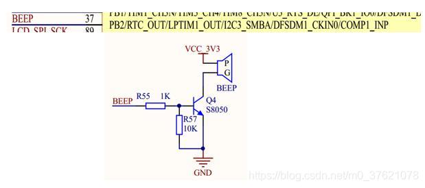
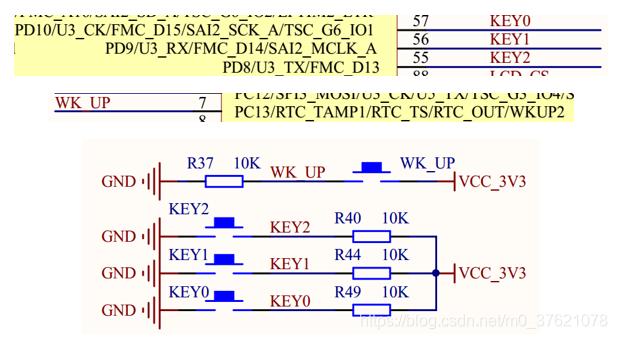
从上图可知,STM32L475上蜂鸣器BEEP接PB2引脚(引脚编号37),KEY0 / KEY1分别接PD10 / PD9引脚(引脚编号分别为57 / 56),在工程中可以直接使用引脚编号,也可以通过宏定义GET_PIN获得引脚编号,下面开始实现工程代码。
在projects\stm32l475_device_sample\applications目录下新建文件pin_sample.c,并在pin_sample.c内编辑工程代码如下:
// projects\stm32l475_device_sample\applications\pin_sample.c

#include "rtthread.h"
#include "rtdevice.h"
#include "board.h"

/* 引脚编号,通过查看STM32L475参考手册获知 */
#define BEEP_PIN    GET_PIN(B, 2)

#define KEY0_PIN    GET_PIN(D, 10)
#define KEY1_PIN    GET_PIN(D, 9)
#define KEY2_PIN    GET_PIN(D, 8)

#define WKUP_PIN    GET_PIN(C, 13)

static void beep_on(void *args)
{
    rt_kprintf("turn on beep!\n");

    rt_pin_write(BEEP_PIN, PIN_HIGH);
}

static void beep_off(void *args)
{
    rt_kprintf("turn off beep!\n");

    rt_pin_write(BEEP_PIN, PIN_LOW);
}

static void pin_beep_sample(void)
{
    /* 蜂鸣器引脚配置为输出模式 */
    rt_pin_mode(BEEP_PIN, PIN_MODE_OUTPUT);
    /* 默认低电平 */
    rt_pin_write(BEEP_PIN, PIN_LOW);

     /* 按键0引脚配置为上拉输入模式 */
    rt_pin_mode(KEY0_PIN, PIN_MODE_INPUT_PULLUP);
    /* 绑定中断回调函数,下降沿触发模式,回调函数名为beep_on */
    rt_pin_attach_irq(KEY0_PIN, PIN_IRQ_MODE_FALLING, beep_on, RT_NULL);
    /* 使能中断 */
    rt_pin_irq_enable(KEY0_PIN, PIN_IRQ_ENABLE);

    /* 按键1引脚配置为上拉输入模式 */
    rt_pin_mode(KEY1_PIN, PIN_MODE_INPUT_PULLUP);
    /* 绑定中断回调函数,下降沿触发模式,回调函数名为beep_off */
    rt_pin_attach_irq(KEY1_PIN, PIN_IRQ_MODE_FALLING, beep_off, RT_NULL);
    /* 使能中断 */
    rt_pin_irq_enable(KEY1_PIN, PIN_IRQ_ENABLE);
}
/* 导出到 msh 命令列表中 */
MSH_CMD_EXPORT(pin_beep_sample, pin_beep sample);
- 1
- 2
- 3
- 4
- 5
- 6
- 7
- 8
- 9
- 10
- 11
- 12
- 13
- 14
- 15
- 16
- 17
- 18
- 19
- 20
- 21
- 22
- 23
- 24
- 25
- 26
- 27
- 28
- 29
- 30
- 31
- 32
- 33
- 34
- 35
- 36
- 37
- 38
- 39
- 40
- 41
- 42
- 43
- 44
- 45
- 46
- 47
- 48
- 49
- 50
- 51
- 52
在env中执行sons --target=mdk5编译并生成Keil MDK V5工程,打开MDK5工程编译无报错,烧录到我们的STM32L475潘多拉开发板内,运行结果如下:
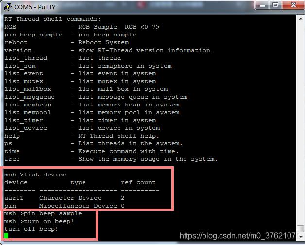
通过list_device查看设备列表PIN设备已启用,运行导出的自定义命令pin_beep_sample后,按下KEY0蜂鸣器响起,按下KEY1蜂鸣器停止,运行结果跟预期一致。
该工程源码下载地址:https://github.com/StreamAI/RT-Thread_Projects/tree/master/projects/stm32l475_device_sample
评论记录:
回复评论: